
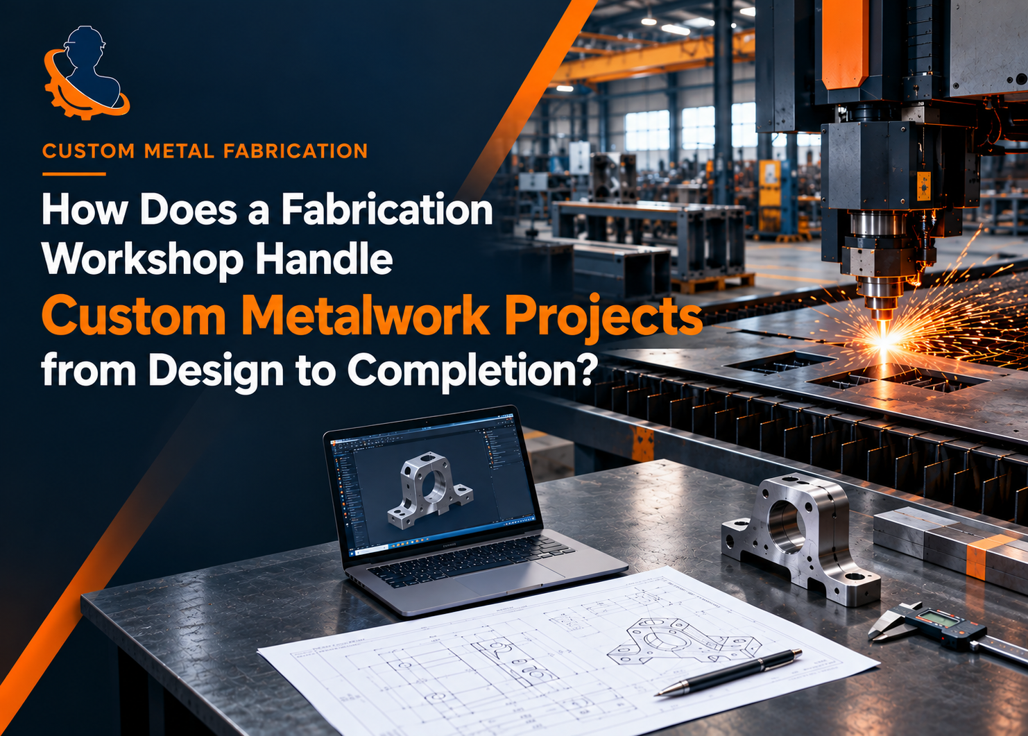
How Does a Fabrication Workshop Handle Custom Metalwork Projects from Design to Completion?
How Does a Fabrication Workshop Handle Custom Metalwork Projects from Design to Completion?
Custom metalwork transforms an initial requirement into a component, structure, enclosure, platform, or complete assembly built for a purpose. The process demands much more than cutting and joining metal. It brings together engineering, material knowledge, skilled workmanship, inspection, documentation, and disciplined project control. A capable fabrication workshop manages these elements as one connected operation. From the first discussion to final delivery, every stage affects accuracy, durability, safety, cost, and lead time. Sarojini Group follows this structured approach to help industrial clients move from an idea to a finished metal solution that meets defined project needs.
Starting with the Client’s Operational Requirement
Every custom project begins with a clear account of what the finished item must do. The client may need a machine frame, pressure-related assembly, storage tank, duct, support structure, access platform, conveyor component, equipment enclosure, or replacement part. Workshop teams first collect relevant drawings, sketches, dimensions, site details, performance expectations, preferred materials, quantities, and delivery targets.
The discussion also covers operating loads, temperature, corrosion exposure, vibration, installation conditions, maintenance access, surface finish, and applicable codes. These details prevent the project from becoming a drawing exercise detached from real operating conditions. When information remains incomplete, engineers identify assumptions and request clarification before production begins.
Assessing Feasibility and Defining the Scope
Once the requirements are clear, the technical team studies whether the proposed metalwork can be manufactured safely, economically, and within the requested schedule. This feasibility review considers available machinery, material sizes, forming limits, welding access, tolerances, inspection needs, lifting arrangements, and transport restrictions.
The team then defines the scope. A sound scope states what the workshop will design, procure, fabricate, inspect, finish, assemble, pack, and deliver. It also identifies client-supplied information, exclusions, approval stages, and responsibilities for site installation. Clear boundaries reduce commercial disputes and make progress easier to measure.
Developing the Engineering Design
Design converts the approved concept into precise manufacturing information. Engineers prepare two-dimensional drawings or three-dimensional models showing geometry, dimensions, connections, hole locations, weld details, tolerances, materials, finishes, and assembly relationships. For load-bearing work, calculations may confirm strength, stability, deflection, fatigue resistance, or support requirements.
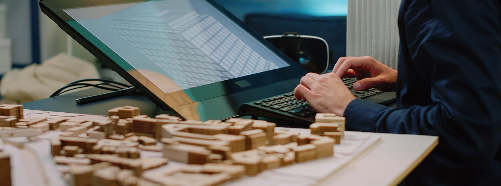
Digital models allow teams to review fit, detect clashes, calculate weight, plan assemblies, and visualise difficult areas before cutting begins. Design personnel also consider practical production matters. They ensure that welders can reach the joints, tools can form the parts, fasteners remain accessible, and sections can pass through workshop doors or travel safely by road.
Drawings normally pass through an internal check before reaching the client for approval. The checker verifies dimensions, specifications, interfaces, notes, and revision status. Client approval establishes the production baseline. A controlled revision system then prevents employees from using superseded drawings after a change.
Selecting the Right Metal and Consumables
Material selection has a direct effect on strength, service life, appearance, weight, weldability, and cost. Depending on the application, a project may use carbon steel, stainless steel, aluminium, alloy steel, galvanised sheet, or another specified grade. The choice should reflect operating conditions rather than price alone.
For example, stainless steel may suit hygienic or corrosive settings, while structural carbon steel can provide an economical solution for frames and platforms. Aluminium offers low weight and good corrosion resistance but requires suitable welding practices and careful control during fabrication. Engineers also evaluate thickness, section shape, availability, and compatibility with coatings or connected materials.
Planning Production Before Cutting Starts
Production planning translates approved drawings into an orderly sequence of work. Planners break the job into parts and assemblies, prepare bills of materials, estimate labour hours, reserve machines, identify outsourced processes, and schedule inspection points. They also coordinate material availability with the promised completion date.
A fabrication workshop must plan the sequence carefully because one operation can affect the next. Forming before cutting certain features may protect dimensional accuracy, while machining after welding may help achieve a critical final tolerance. Large projects often use subassemblies so different teams can work in parallel before final integration.
Cutting and Preparing Individual Parts
Fabrication begins when technicians mark and cut the approved material. Workshops may use sawing, shearing, punching, laser cutting, plasma cutting, oxy-fuel cutting, or waterjet cutting, depending on the material, thickness, tolerance, edge quality, and production quantity.
Computer-controlled equipment can reproduce complex profiles accurately from digital files. However, machine capability does not remove the need for human checks. Operators confirm material identity, plate orientation, program revision, dimensions, and cutting allowances before starting. They may arrange parts efficiently on a sheet or plate to reduce scrap.
After cutting, workers remove slag, burrs, and sharp edges. They bevel weld joints where required, drill or machine holes, and label parts so they remain traceable through production. Inspectors check key dimensions before the parts move forward. Finding an error at this point costs far less than finding it after a complete assembly has been welded.
Forming, Rolling, and Machining Components
Many projects require flat metal to take a new shape. Press brakes create controlled bends, rolling machines form cylinders or curves, and presses produce repeated shapes. Operators account for spring-back, grain direction, bend allowance, minimum radius, and tooling limitations. Incorrect settings can crack a component, distort holes, or produce an angle outside tolerance.
Machining supports parts that require close fits or precise surfaces. Lathes, milling machines, drills, and computer-controlled machining centres may produce shafts, flanges, slots, threads, bushes, and mounting faces. The workshop coordinates machining with welding and heat treatment because heat can alter final dimensions.
Fitting and Assembling the Metalwork
Fit-up brings the prepared parts together according to the drawing. Fabricators use measuring tools, squares, levels, clamps, fixtures, and tack welds to establish position and alignment. They verify diagonals, elevations, hole centres, joint gaps, and overall dimensions before permanent joining.
This stage demands patience because small errors can accumulate across a large assembly. A misplaced bracket may interfere with equipment, while an incorrect flange angle may prevent a pipe connection at site. Qualified supervisors check critical fit-up points and release the assembly for welding only after it meets the acceptance criteria.
Large structures may receive a trial assembly inside the facility. This confirms that modules connect correctly and gives the team an opportunity to mark matching sections. Trial assembly can substantially reduce site work, where access, weather, time, and lifting equipment create additional constraints.
Welding with Controlled Procedures
Welding permanently joins components and often determines the integrity of the finished product. The chosen process may include shielded metal arc, gas metal arc, flux-cored arc, gas tungsten arc, or submerged arc welding. Selection depends on joint design, material, thickness, position, quality level, and production rate.
Controlled work uses approved welding procedures that state essential parameters such as consumable type, current range, joint preparation, position, preheat, interpass temperature, and shielding gas. Qualified welders perform the work within these limits. Supervisors also manage distortion through balanced welding sequences, clamps, presetting, heat control, and suitable joint design.
Welders clean each joint and inspect intermediate passes where necessary. They protect sensitive metals from contamination and control consumables to prevent moisture-related defects. After welding, they remove spatter and temporary attachments without damaging the parent metal.
Managing Quality Throughout Production
Quality control works best as a continuous process rather than a final inspection. An inspection and test plan identifies checks at defined stages, along with acceptance criteria, responsible personnel, records, and client witness points. This structure keeps problems from moving unnoticed into later operations.
Inspectors verify material certificates, dimensions, fit-up, weld preparation, welder qualifications, procedure compliance, surface condition, coating thickness, and final assembly. They use calibrated instruments suited to the required accuracy. Any nonconforming item receives identification, review, and an approved correction before work continues.
Visual weld inspection can reveal surface cracks, undercut, incomplete profiles, porosity, or poor finish. Where specifications demand deeper examination, trained personnel may use dye penetrant, magnetic particle, ultrasonic, or radiographic testing. Pressure or leak testing may apply to tanks, piping, and sealed equipment. The project specification determines the correct method and acceptance standard.
Surface Preparation and Protective Finishing
A suitable finish protects metal and supports the required appearance. Before coating, workers remove oil, dirt, rust, scale, weld residue, and other contamination. Preparation may involve solvent cleaning, grinding, power-tool cleaning, pickling, or abrasive blasting. The specified cleanliness and surface profile depend on the coating system and service environment.
Finishing options include industrial paint, powder coating, hot-dip galvanising, electroplating, passivation, polishing, and specialised protective systems. Coating personnel control mixing, application conditions, wet-film thickness, curing time, and final dry-film thickness. They also protect machined faces, threads, identification plates, and areas intended for site welding.
Careful handling after finishing prevents scratches, dents, and coating damage. When damage occurs, workers repair it using an approved system compatible with the original finish.
Final Assembly, Functional Checks, and Documentation
The workshop then installs specified bought-out items, fasteners, guards, hinges, seals, grating, or mechanical components. Technicians check movement, alignment, clearances, fastening torque, and interface dimensions. If the project contains moving parts, a functional test confirms that the assembly operates as intended within safe limits.
Final inspection verifies the completed item against drawings, specifications, and approved changes. The documentation pack may include material certificates, inspection reports, welding records, test results, coating reports, calibration references, photographs, packing lists, and as-built drawings. Proper records give the client evidence of compliance and support future maintenance or modification.
Packing, Transport, and Site Completion
Delivery planning begins well before fabrication ends, especially for oversized or heavy items. Engineers may divide a structure into transportable modules and design lifting points into the assembly. Logistics personnel confirm vehicle capacity, route restrictions, permits, loading sequence, centre of gravity, and unloading arrangements.
Packing protects surfaces, openings, loose parts, and precision features. Clear markings identify lifting locations, orientation, assembly sequence, and package contents. The workshop secures every item to prevent movement during transit.
If installation forms part of the scope, the site team follows approved drawings and safe work procedures. It checks foundations, interfaces, levels, and access before erection. After assembly, the team completes connections, touch-up coating, alignment, testing, and handover records. Client representatives can then inspect the installed work and close outstanding points.
Conclusion
Custom metalwork moves successfully from design to completion when every activity follows controlled technical information. Requirement gathering establishes purpose; engineering defines the solution; procurement secures suitable material; skilled production creates the parts; and inspection verifies conformity. Finishing, documentation, transport, and installation then protect the value created inside the workshop. By coordinating these stages, Sarojini Group supports metalwork projects that respond to practical operating needs, dimensional requirements, safety expectations, and delivery commitments. A structured process also gives clients clearer decisions, stronger traceability, and confidence at each approval point.
FAQs
How does a fabrication workshop maintain quality during metalwork production?
It uses approved drawings, material traceability, qualified personnel, controlled welding procedures, calibrated measuring equipment, and stage-based inspections. Depending on the specification, quality checks may include dimensional verification, visual examination, non-destructive testing, pressure testing, coating measurement, functional trials, and review of final manufacturing records.
Can a fabrication workshop manufacture from a sketch or physical sample?
Yes, provided the team can obtain accurate dimensions and confirm performance requirements. Engineers can convert a sketch, sample, or site measurement into controlled production drawings. The client should review and approve these drawings before manufacturing starts, particularly when the new item must connect with existing equipment.
How long does a fabrication workshop take to complete custom metalwork?
The duration depends on design complexity, approval speed, material availability, production capacity, testing, finishing, quantity, and transport arrangements. A simple component may require a short cycle, while a large engineered assembly may take several weeks or months. A detailed schedule should identify approval, procurement, production, inspection, and delivery milestones.
NEWSLETTER
Sign up your mailing list to get lastest Updates.